Welcome to my robotics portfolio! Here, you’ll find a collection of my most exciting robotics projects, in order of reverse chronology. From designing cutting-edge data-driven motion algorithms for mobile aquatic robots to building an 8-foot tall musical spiderweb to NASA rover design challenges, these works showcase my engineering creativity and technical skills.
AmoeBot Control
This project was the capstone for my PhD! It was exciting to carry the ball on this project from inception early on in my doctoral studies all the way to implementation on a real-time robotic system. It was a collaboration with researchers from UCSD that I feel effectively showcased the breadth of impact my research could have on real-time robot control. I’m currently working on a journal paper draft that discusses this project!
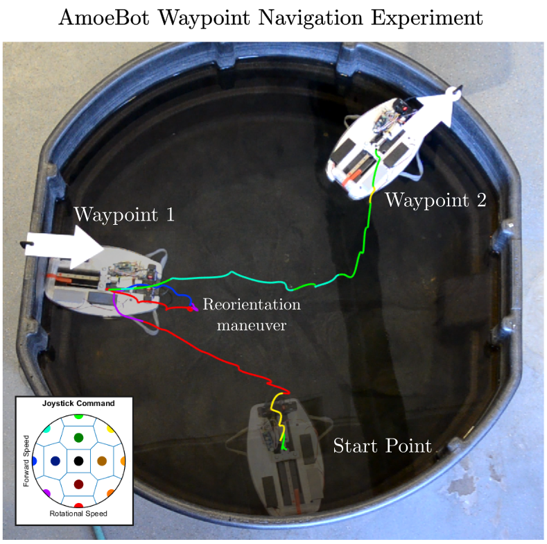
The AmoeBot is a novel aquatic robot developed by our collaborators at UCSD that locomotes across the surface of water using soft buckling tape-spring fins.
Using experimental data collected at UCSD, I performed geometric system identification on the robot’s hydrodynamic behavior. Using the model that best-fit the experimental data, I performed dynamic simulations to optimize actuator motion for desired sets of locomotive behavior.
Once we had the collection of actuator motion plans that resulted in convenient locomotive actions (e.g. turning, forward, backward), I mapped each motion plan to a position on a joystick and implemented algorithmic control laws to govern the execution of each motion plan.
Finally, we placed the robot in a test tank, used the joystick to select motion control policies, and streamed these actuator command sequences over WiFi to a real-time operating system (RTOS) onboard the robot that queued up the commands. It drove well!
There were a few technical pieces to this project that were especially interesting for me to develop. The first was the model identification process, which we performed using experimental data gathered from a test tank in which the system was held stationary and attached to a 6DoF load cell for sensing. A GIF of one experimental trial can be seen to the right.
Similar constraints are often used for experiments involving locomoting systems, because they make it simple to gather propulsive data. However, the constraints involved in fixing the system to the load cell change the fluid interaction! If the system were unconstrained, the robot would accelerate and develop relative velocity with respect to the fluid, altering the fluid forces that would result from actuator shape changes.
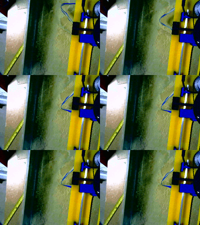
Because of this complexity, such experiments are typically used as simple measures of system efficacy rather than to actually perform system identification or develop useful motion plans. It seems intuitive, though, that they likely contain the necessary data to perform both of these tasks. This was the problem that I set out to solve!
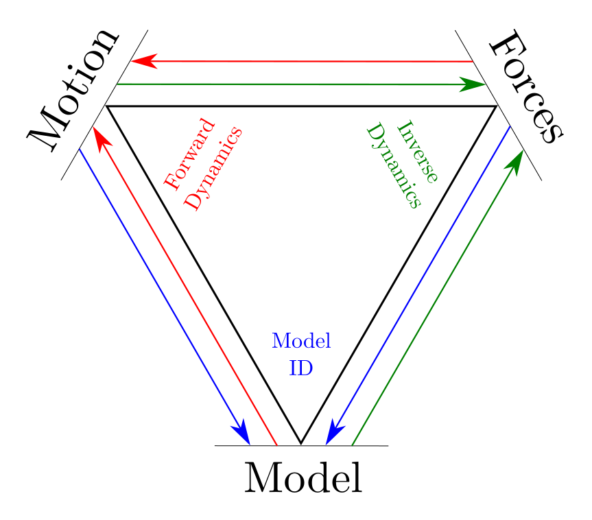
The key insight for this project was to start thinking of the three components of the system dynamics as a triangle (pictured to the left), where any two corners of the triangle can be used to back out the third.
Forward dynamics, where the system model and the actuator forces are used to predict motion, and inverse dynamics, where the system model and desired motion are combined to estimate required forces, are well studied.
We realized that for the third option, that of model identification, we can perform a similar rearrangement of the equations of motion to back out the dynamic parameters that best explain the combination of system motion and applied/sensed forces.
If this process of equation rearrangement is performed just after calculating the system Jacobians, the constraints present in the experimental data are encoded in the system motion (or lack thereof), and the resulting model can be abstracted to both constrained and unconstrained cases. This allowed us to estimate the hydrodynamic parameters that governed the robot’s locomotive behavior, to implement a simulation of this model, and to optimize for behavior that moves the robot in desired directions. Check out the results below to see how the real-time implementation of the geometric control behaves!
Waypoint Navigation
Left hand side: AmoeBot navigating between arrow waypoints, which are clamped to the side of the tank
Bottom right: Joystick commands given to the control software by the AmoeBot pilot (me)
Top right: Shape execution of the motion plan that corresponds to the desired locomotion behavior
Figure-Eight Navigation
Similar video layout as above, but for a figure-eight navigation around two aluminum posts in the tank.
Although I am manually piloting the AmoeBot and broadly telling it which direction I want it to go, the execution of that high-level objective into robot actuator signals is entirely driven by the autonomous process of the geometric algorithm interpreting the constrained experimental data and turning it into motion plans.
I think this geometric process of model identification and control optimization has a lot of potential applications for the field of robotics! Right now I’m most interested in how similar model identification process and motion optimization can be used online to regress dynamic descriptors for objects that a robot might be interacting with, such as a payload carried by a humanoid or a branch being moved out of the way for fruit-picking.
Soft Origami Thruster
I worked on this project with my friend and colleague Ali Jones, who recently defended their masters degree in robotics with an emphasis on soft actuation!
The inspiration for this project is the sea salp, a very fun oceanic colonial organism formed of chains of individual jellyfish-like zooid elements.
As part of a larger collaboration studying how we can draw inspiration in robotic design from these fascinating creatures, Ali and I began to examine what a small robot thruster mimicking salp behavior might look like. Ali specialized in developing small twisted-and-coiled actuators (TCAs) that could be used to drive robot motion. Effectively, they are small strings contract about half of their length with electrical current is run through them. When I heard that Ali wanted to make an origami actuator driven by the contraction of their TCAs, I rushed to jump onboard the project, as I have been doing origami design since my early childhood and quite enjoy the challenges involved.
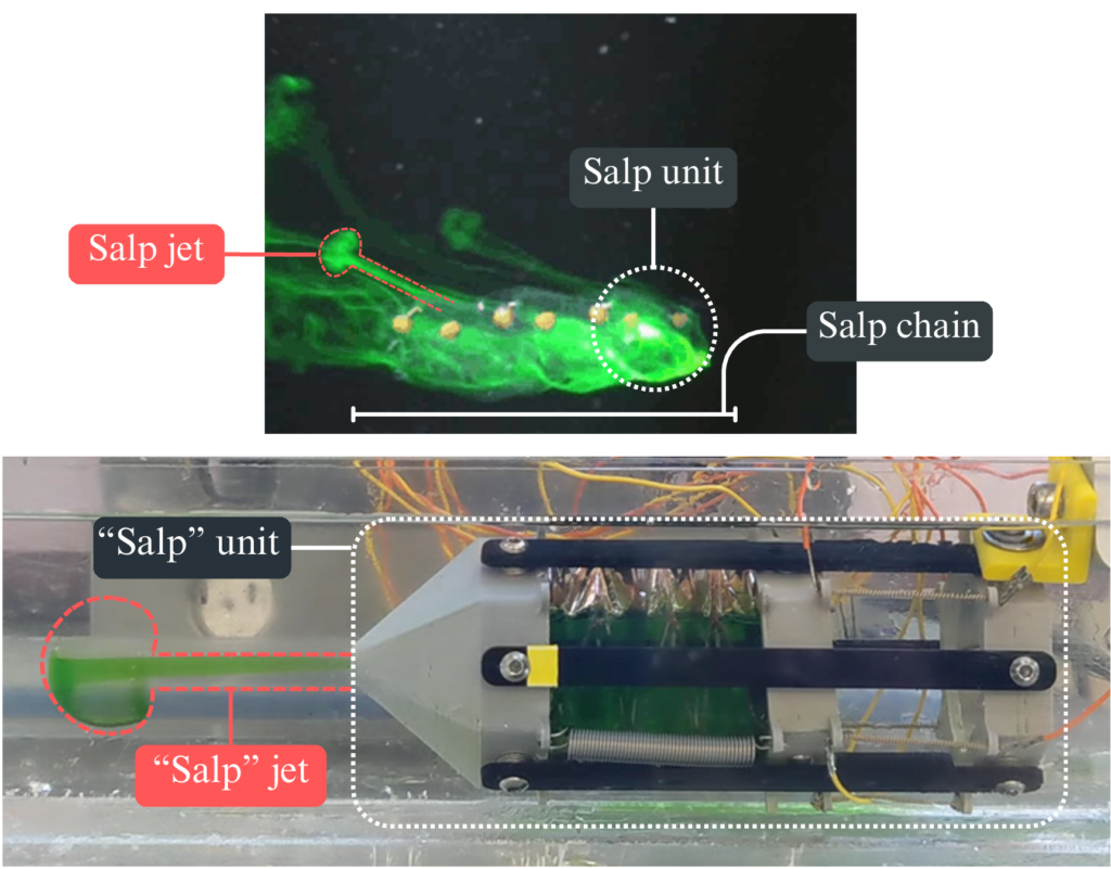
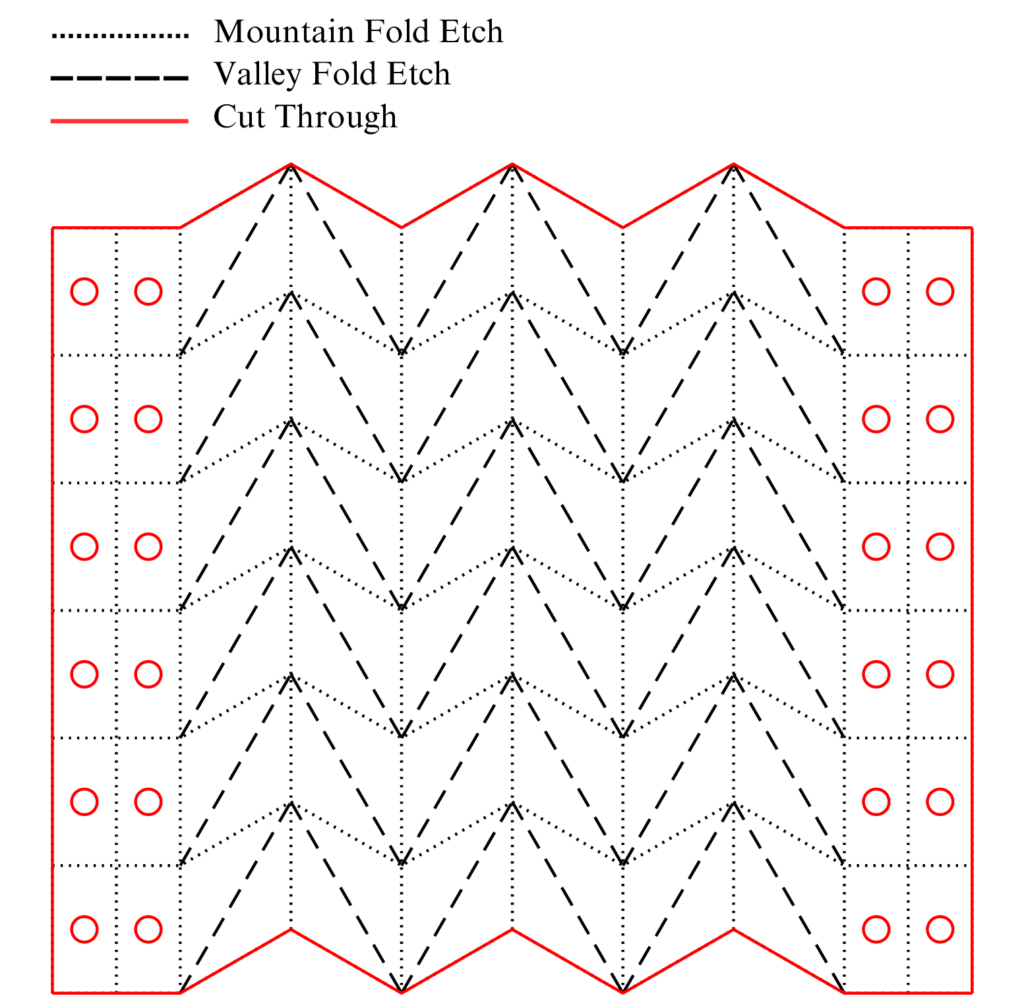
To assist in the project, I designed the modular collapsible origami bellows for the actuator, the 3D printed mount and nozzle for the thruster mechanism, and manufactured the thrusters for Ali to test and validate.
Manufacturing these thrusters was fairly tricky! To enable the TCAs to actuate the bellows structure, it needed to be made of incredibly thin material, and it had to be waterproof to be fit for purpose. This drove us to use 0.002″ PET plastic for the bellows material. I spent quite a bit of time adjusting laser cutter settings to automate the manufacturing process, as it is difficult to ablate the creases in the origami design without cutting through the material entirely. I also iterated quite a few times through the other related hardware, adjusting nozzle parameters and mounting methods.
We found that this design could produce thrust comparable to that of the biological salp thrusters. Although there need to be substantial improvements to the thrust force before it would be practically feasible for a real-life robot, we feel that this design is exciting and novel and are currently working to submit a conference paper in September based on this work!
Spiderharp
The Spiderharp is a very fun spin on our spider research that manifested as a musical collaboration with Dr. Chet Udell, our resident Spiderharp musician at OSU.
Using some of our previous research studying how vibration signals propagate through spiderwebs, we built an algorithm to identify the types of information in spiderweb vibrations that could tell a spider where a disturbance in the web was located. We then built an 8-foot tall spiderweb out of an aluminum frame and parachute cord and mounted a “spider” consisting of 8 accelerometers in the center of the web that reads web signals. The onboard harp compute uses this algorithm to estimate where web plucks are occurring. We then implement a mapping from web location to musical note and play the musical signal through up to 8 nearby speakers surrounding the audience.
It is easily our lab’s most popular form of outreach, and is quite fun to set up and play.
My contribution to this project was to assist in the mechanical design and manufacturing, design and implement a few of the embedded systems within the harp such as the web tensioner sensors and electronics, construct and deploy the harp for events and laboratory demonstrations, and replace components and perform product lifecycle management.
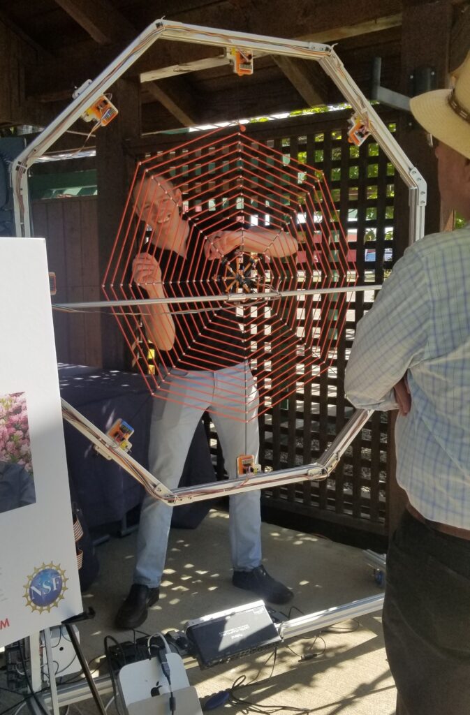
We had a featured article through Oregon Public Broadcasting about this project in October 2023. Check it out if you want to hear more from Ross and Chet about this project or to watch a video about how the harp works and hear it played! Catch me scattered throughout the video in my “long hair don’t care” phase.
Spiderweb Vibrometry
For this project, I acted as the engineering liaison for a group of arachnologists working in California for the USDA. I helped implement no-contact computer vision sensing to study how signals propagated through spiderwebs, analyze and extract spider communications during female-female interactions, and study through video analysis what modalities of vibration spiders likely feel while in their webs.
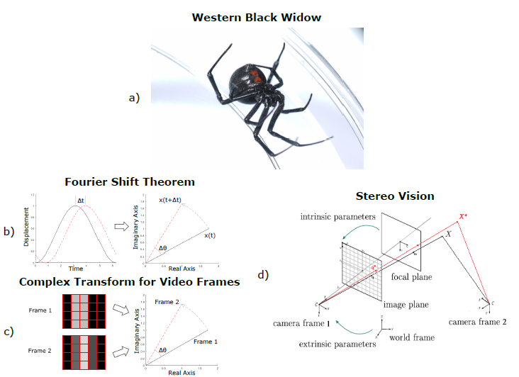
To enable these web-vibration measurements, I used previously developed computer vision methods of optical flow analysis on synchronized sets of video data captured from two adjacent high-speed cameras. From the resulting motion data, I used stereo vision techniques to combine the 2D motion estimates from each of the video streams into 3D vibration data across the breadth of the video frames.
This work resulted in two different journal papers, one methods paper focused on documenting the vibration measurement technique and one analysis paper focused on discussing spider behavior and signal properties.
NASA Rover Design Challenge
This is one of the robotics projects I’m most proud of! My senior year of my aerospace engineering undergrad studies, I approached Dr. David Miller at the University of Oklahoma, and asked if I could do my honors research project with him, as he specialized in space robotics. He told me to get a small group of people together and send a submission to a NASA rover design challenge scheduled to take place at NASA-JSC at the end of the year. I accepted this research project, managed to convince a few friends from former projects to become interested, and founded the “Sooner Rover Team,” which is still around at OU to this day!
After getting our design proposal accepted and funded for $10,000, I served as chief engineer and worked incredibly hard to design and build this robot over the next 8 months with my team.
The design challenge was essentially a remote Easter-egg hunt, with the rover having to be teleoperated from the “mission control” on the home campus to explore the rover test yard in Houston TX at NASA-JSC and search for and retrieve colored rock “samples.” There were other associated challenges such as a rover rescue mission and races.
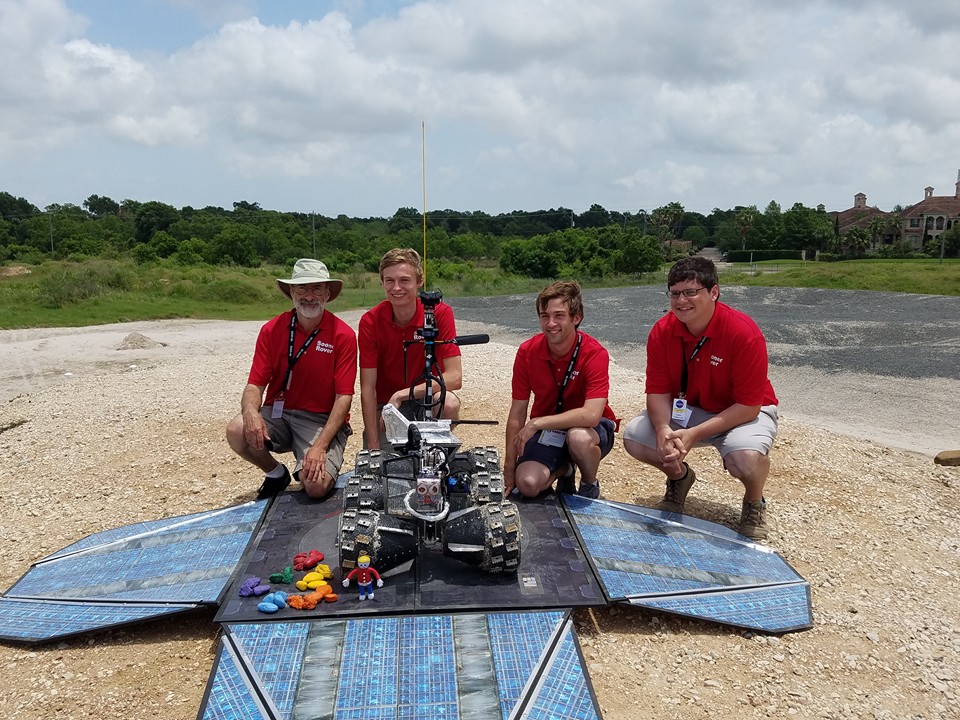
We won this competition by quite a large margin! We collected more samples than the other 7 university competition teams combined, beating the previous course record for the competition in just over 23 minutes of our hour-long runtime, and won the 1st place price of $6,000. It was a blast to blitz together this hyper-competent machine over just a few months through a congregation of hardware, electrical, and software engineering. This success was part of how I got my first post-college job at Mission Control for the International Space Station, and I started professional work at NASA-JSC just a few months later!
Check out a clip of some of the highlights from the competition, where you can catch some glimpses of the super cool physical proxy we used to control the manipulation arm. Alternatively, watch our midpoint review to see how much progress we had made in just 4 months of design work! I always enjoy watching that little beast haul itself over terrain that should cause major breakdowns.
Persistence of Vision Wand
Unfortunately I have lost most pictures of this project, which holds a special place in my heart for two particular reasons. The first is that this was my first ever major Arduino project! This was made the summer after my freshmen year of my undergraduate work, where I was first discovering my love for robotics, software, and embedded systems. The second reason was that it was one of my first interactions with my now-partner of over 10 years, Samantha Stroup!
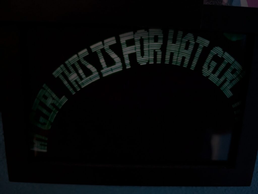
This project was pretty simple in nature. It was an Arduino Uno connected to a long chain of serially addressable LED lights affixed to a wooden mount and handle. By flashing patterns to the row of lights very quickly and waving it through the air, it could “write” short messages, which would appear to float and remain in the air for a second due to persistence of vision effects in the eye.
A few months prior, I had introduced myself to my now-partner over a long elevator ride by telling her that I thought she was cute and that I called her “Hat Girl” due to her good choice in hats. As we were texting later that summer, I told her about my project and took this picture for her.
This picture still hangs on the wall of our house to this day! This might not be my most technically involved project, but it is almost definitely my cutest.
